
0 引言
1 数据来源和方法
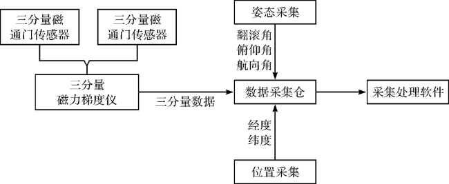
1.1 数据采集
1.2 数据处理
1.2.1 单个三分量磁通门传感器的校准
1.2.2 两个在三分量磁通门传感器的互校准
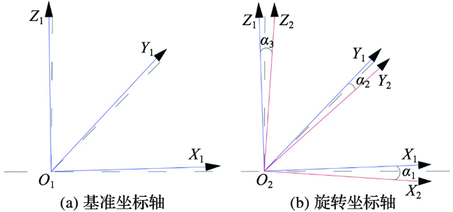
图3 坐标轴旋转示意图(两个磁力传感器的坐标系分别为O1X1Y1Z1和 Y2Z2,以 Y1Z1坐标系为基准,三个旋转角分别为α1、α2、α3。图中虚线表示虚拟理想正交坐标轴。) Fig.3 Schematic diagram of axis rotation (The coordinate systems of the two magnetometers are O1X1Y1Z1 and O2X2Y2Z2, Based on the axes O1X1Y1Z1, the three rotation angles are α1,α2,α3. The dotted line is the virtual ideal orthogonal coordinate axis.) |
1.2.3 姿态校正
1.3 外符合精度评价
2 结果与分析
2.1 磁源体边界位置
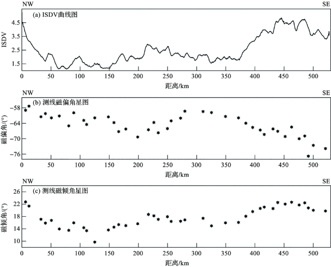
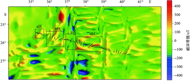
图9 磁边界走向图(图中黑色线段的中心点对应磁边界的位置;长线段的方向对应磁边界的磁偏角,线段长度与磁边界磁倾角的余弦值成正比;短线段的长度与磁边界矢量的标准差成正比。) Fig.9 Strike diagram of magnetic boundary (The central point of the black line segment in the figure corresponds to the position of the magnetic boundary. The direction of the long line segment corresponds to the magnetic declination angle of the magnetic boundary, and the length of the line segment is proportional to the cosine value of the magnetic inclination angle of the magnetic boundary. The length of the short line segment is proportional to the standard deviation of the magnetic boundary vector.) |